Lesson Objective
- Be able to identify OR, AND and NOT Logic Gates.
- Be able to create Truth Tables for a Logic Circuits.
KS3, GCSE, A-Level Computing Resources
Electronic circuits that perform Binary functions are called logic gates. Logic Gates form the basis of all logic circuits.
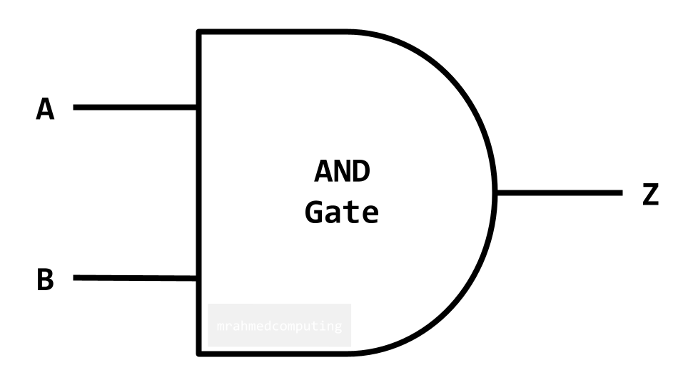
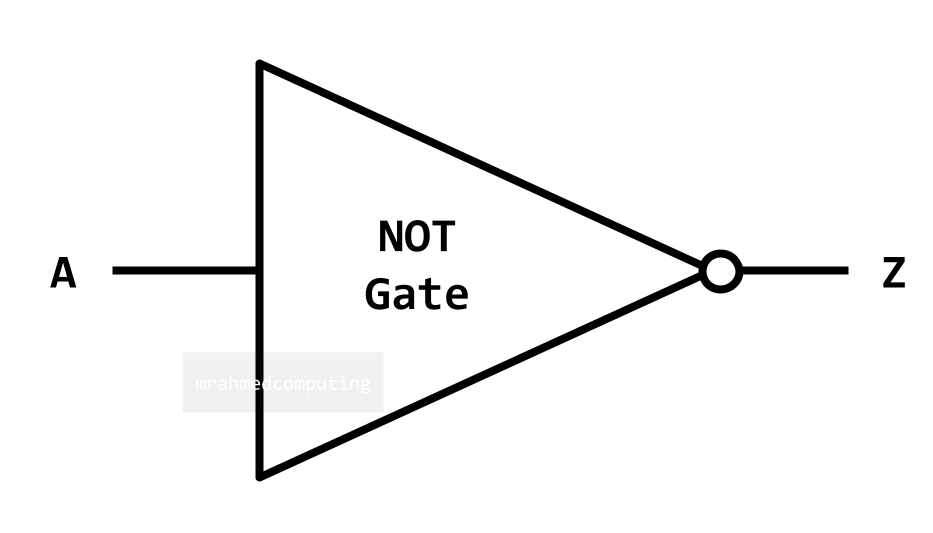
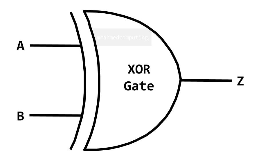
Logic Gates represent Boolean Equations. Each Boolean function is represented by a different symbol.
A truth table shows the results of Boolean equation from all possible combinations of inputs. They are used to show all possible outcomes from Boolean equations and logic gate diagrams. The truth table and logic gate symbol for show on the right of the screen. Or below on mobile browsers.
For an AND Gate the output is TRUE only if ALL inputs are TRUE.
Boolean Algebra Notation:

| A | B | Z |
|---|---|---|
| 0 | 0 | 0 |
| 0 | 1 | 0 |
| 1 | 0 | 0 |
| 1 | 1 | 1 |
For an OR Gate the output is TRUE if EITHER/ALL inputs are TRUE.
Boolean Algebra Notation:

| A | B | Z |
|---|---|---|
| 0 | 0 | 0 |
| 0 | 1 | 1 |
| 1 | 0 | 1 |
| 1 | 1 | 1 |
For a NOT Gate the output is the OPPOSITE (inverse) of the input.
Boolean Algebra Notation:

| A | Z |
|---|---|
| 0 | 1 |
| 1 | 0 |
For an XOR Gate the output is TRUE if only ONE input is TRUE.
Boolean Algebra Notation:

| A | B | Z |
|---|---|---|
| 0 | 0 | 0 |
| 0 | 1 | 1 |
| 1 | 0 | 1 |
| 1 | 1 | 0 |

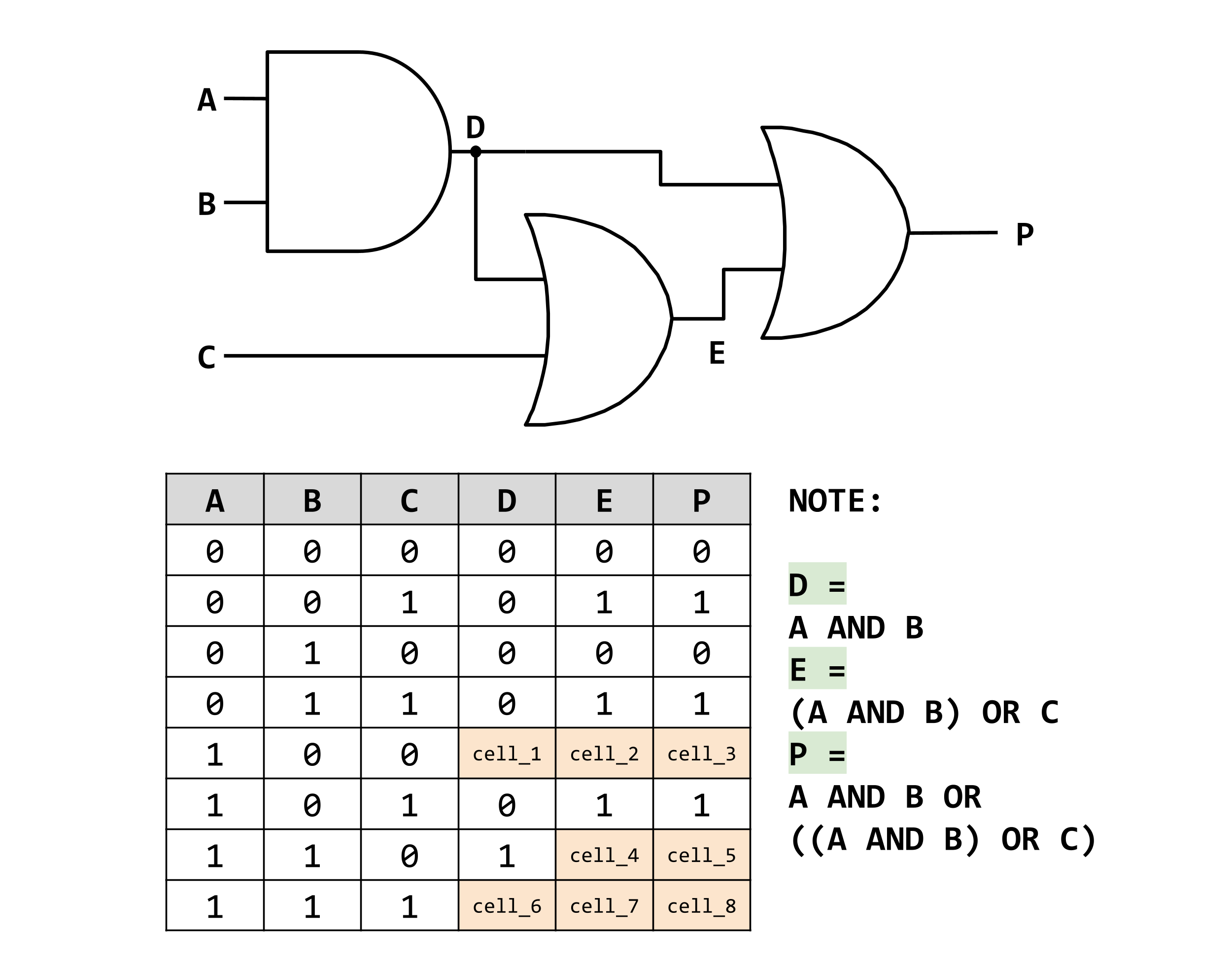
Identifing Expressions and Complteting a Truth Table
The output expressions have been labelled and noted in the diagram.
Can you work out the outputs for the remaining cells?